 Applications
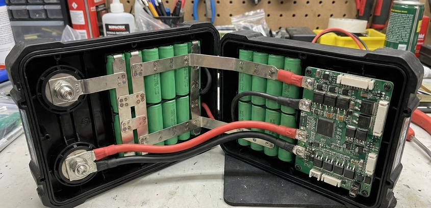
High-Drain Packs for Power Tools
A cordless circular saw can pull 50 Amps in a heartbeat. If you rebuild its battery with standard laptop cells, you will create a fire hazard. In this high-performance guide, we analyze the specific chemistry of "High Drain" cells, the necessity of double-layer nickel strips, and how to safely rebuild Milwaukee, DeWalt, and Makita packs for more torque than they had when new.
08 Jan 2026
Read More