 Solar Systems
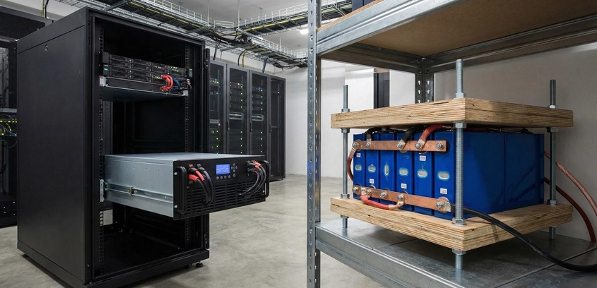
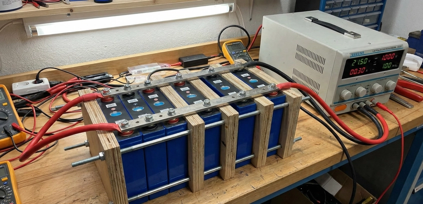
Top Balancing Large Prismatic LiFePO4 Banks
Skipping the top balance is the fastest way to ruin a brand-new $2,000 LiFePO4 bank. In this engineering masterclass, we explain the "Flat Curve" problem, why BMS units cannot fix a mismatched pack, and provide a detailed, step-by-step protocol for parallel saturation to ensure your cells are perfectly synchronized at 3.65V.
07 Nov 2025
Read More