 DIY Projects
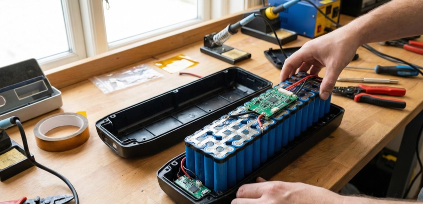
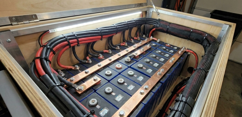
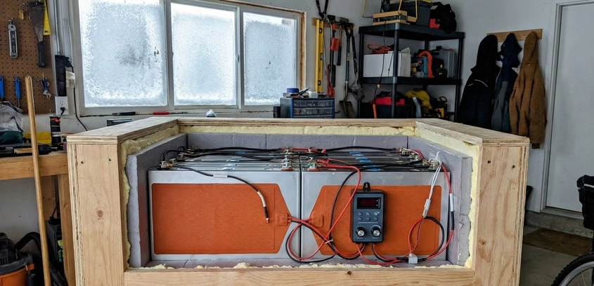
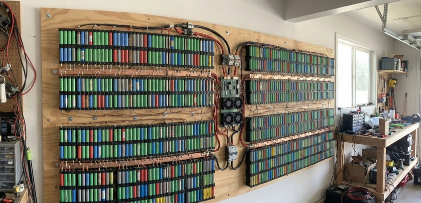
Project: Building a Recycled 18650 Powerwall
The project that defined a generation of DIY energy storage. We break down the engineering of a modular 18650 powerwall using recycled laptop cells, explaining the safety of cell-level fusing, the physics of massive busbars, and the logistics of testing 1,000+ cells for a home-scale energy system.
21 Nov 2025
Read More