 Charging & Safety
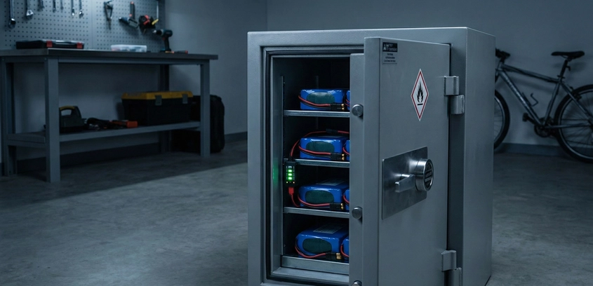
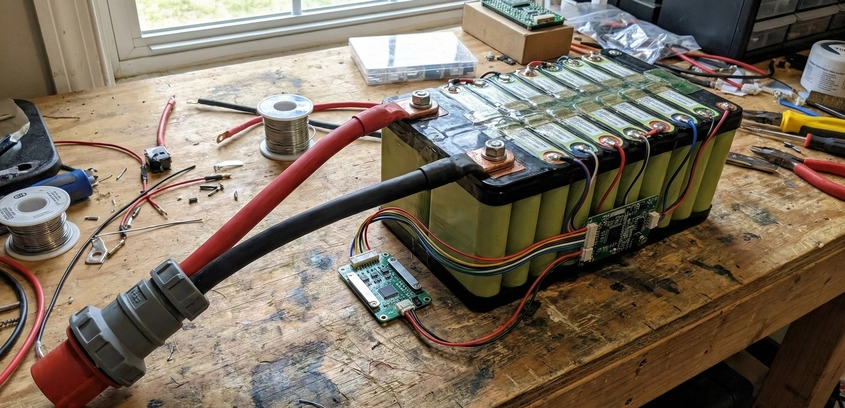
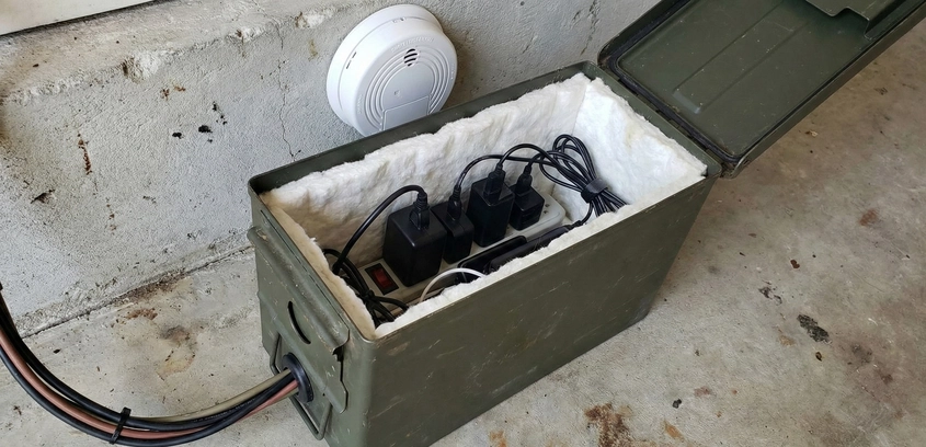
Building a Fireproof Charging Bunker
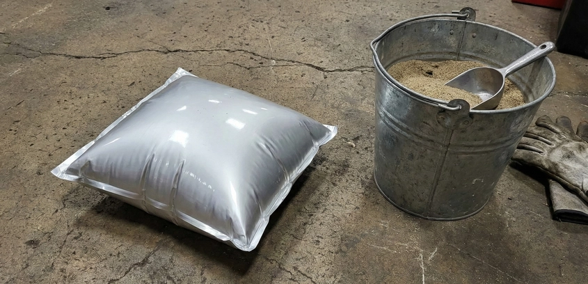
If you are charging massive DIY battery packs, a standard Lipo bag is not enough to protect your home. In this comprehensive safety guide, we walk you through the engineering requirements for a lithium containment bunker, the physics of smoke filtration, and how to build a cinder block or steel station with automated emergency shutoffs.
23 Oct 2025
Read More