 Tools & Equipment
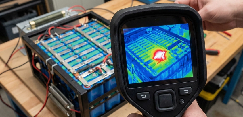
Using Thermal Cameras for Diagnostic Checks
A high-resistance connection is invisible to the eye but glows like a star to a thermal camera. In this diagnostic masterclass, we explain the physics of IR imaging, how to perform a dynamic load test to spot weak spot welds, and why a $200 thermal module is the best safety investment for any battery workshop.
04 Dec 2025
Read More