
 Battery Design & Assembly
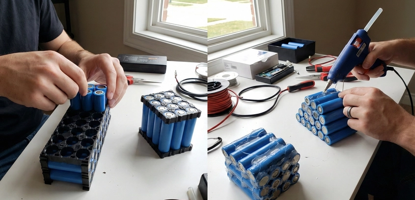
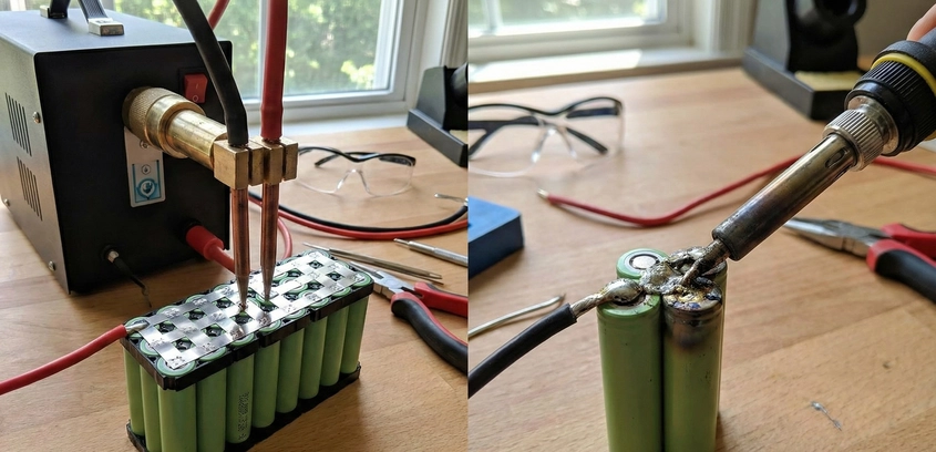
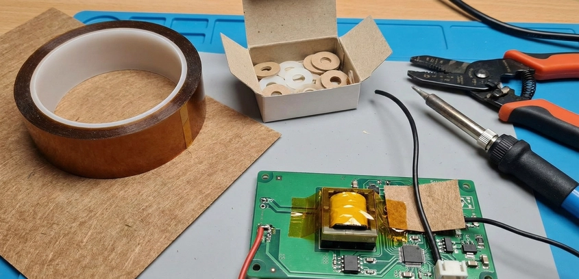
Insulation Guide: Fishpaper, Kapton, and Short Prevention
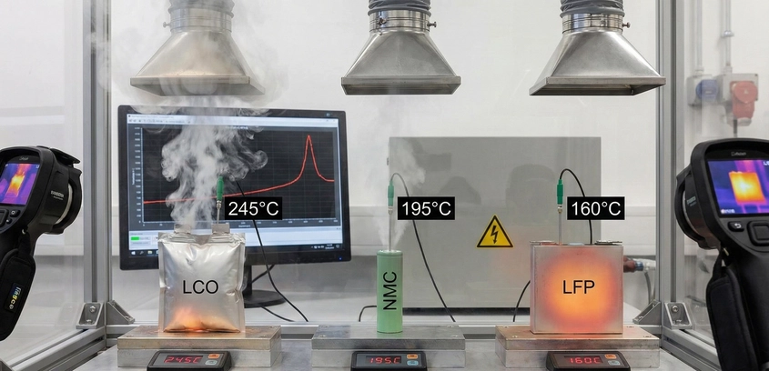
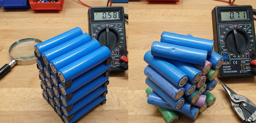
The most common cause of catastrophic battery fires isn't bad chemistry; it's bad insulation. In this safety deep dive, we explore the anatomy of the "Guillotine Short," why PVC shrink wrap is not enough, and the specific material properties of Vulcanized Fiber (Fishpaper) vs. Polyimide (Kapton) that save lives.
23 Sep 2025
Read More