 Troubleshooting & Maintenance
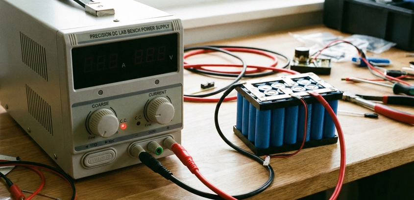
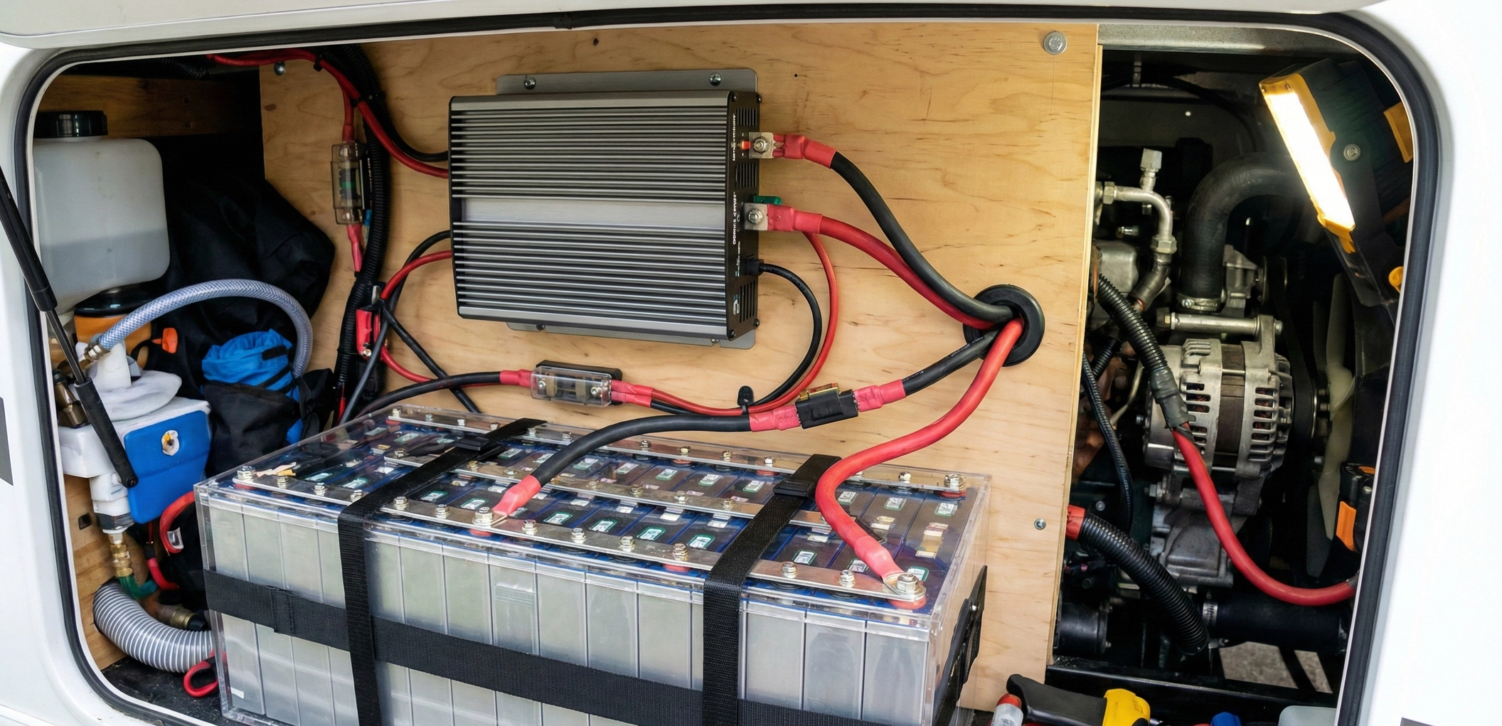
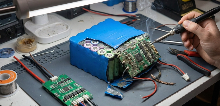
Replacing a BMS in an Existing Pack
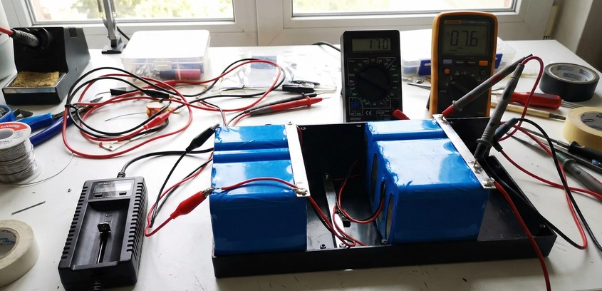
A dead BMS is the most common failure point in DIY packs. Swapping it out is dangerous because you cannot turn the battery off. In this safety-critical guide, we detail the strict disconnection and reconnection sequence required to prevent short circuits and explain why pinout verification is mandatory even if the plug looks the same.
23 Dec 2025
Read More